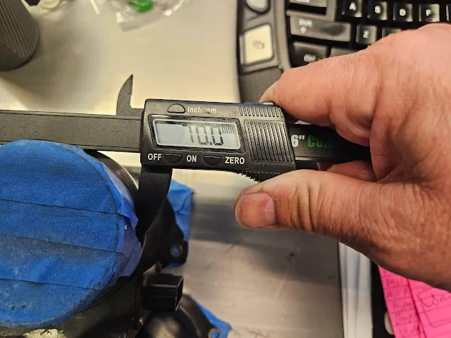
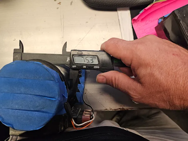
------ --------- OD mm--- RWHP ---- RWHP ---- BHP ------ BHP
No of AFM's ---- -------- 1 ---------- 2 ------------- 1 -------- 2
RB26 ---------- 65 ------- 200 ------ 400 ------- 271 ------ 474
RB20/25 ------ 80 ------- 300 ------ 600 ------- 376 ------ 683
Z32 ------------- 8075---- 340 ----- 685 ------- 415 ------ 763
Q45 ------------ 90 ------- 400 ------ 810 ------- 479 ------ 890
R35/Nissan 70 ----- 300---------600
R35/Nissan 76.5-----350 --------700
R35/Nissan 88.9-----500--------1000
PMAS HPX 63.5----580 ----- 1160
PMAS HPX 70 -----640------- 1280
PMAS HPX 76.5 ---830 ----- 1660
PMAS HPX 88.9 ---1130 ------2260
This is a decent rule of thumb for MAF flow to horsepower. Like any rule of thumb its not exact, and misses a few factors, but its close enough to eyeball.
N/A and Turbo Engine HP= MAF (g/s) * 1.25
Supercharged Engine HP=MAF (g/s) *1.1
N/A and Turbo Dynojet WHP manual= MAF (g/s) * 1.1
Supercharged Dynojet WHP manual =MAF (g/s) *0.95
As you can see in this HKS chart, a stock MAF at around 5 volts, or maxed out is about 275 g/s, that equates to just about 340 hp at the engine each. I find the OEM sensors are about done by 4.7 to 4.8 volts or 200 g/s which is about 250 at the engine, or 220 at the wheels each.
Strengths of Mass Air Flow
- Extremely accurate fueling and spark delivery across a diverse range of engine conditions (at least while in steady-states): the holy grail for engine management. A properly set-up MAF system can adapt to changes in weather and altitude with ease.
- Minor changes to engine equipment (i.e. headers, minor camshaft changes, intakes that do not significantly alter the placement of the MAF) do not require recalibration of the ECM.
Weaknesses of Mass Air Flow
- MAF systems are extremely intolerant of vacuum leaks. Any leaks between MAF sensor and engine generally cause all manner of odd problems, running lean in most cases due to un-metered air making it into the engine.
- MAF sensors can be extremely sensitive to how they are “clocked” – merely rotating the sensor at a given spot in the intake tract can be sufficient to significantly change its output.
- MAF sensors require laminar flow to read 100% accurately. True laminar fluids do not exist so this introduces some degree of inaccuracy to MAF sensor readings. Placing MAF sensors near bends, size transitions or obstructions where flow is less laminar greatly magnifies this issue.
- A MAF sensor can be a flow restriction in cases where the MAF housing is the smallest portion of the intake system.
- Hot-wire MAF elements are very fragile. Debris can destroy delicate wires easily. Dirt and oil deposits can build up on the sensor element, adversely affecting readings.
- MAF systems have a relatively poor response to transient conditions, such as sudden throttle changes. This is explained by the time it takes air to move from the MAF sensor where it is measured to the cylinder where it can be involved in combustion.
- MAF sensors are not “one-way” sensors – reversion from a camshaft with large amounts of overlap can cause air to be metered on its way in to the engine and then again on its way out resulting in an artificially high MAF reading. This can almost always be fixed by placing the MAF sensor sufficiently far from the throttle body, however doing so comes at the expense of making transient response even worse.
It may seem like there are a lot of weaknesses of MAF systems, but it is truly hard to emphasize just how amazing and important the strengths are. It is no secret that the majority of OEMs today are implementing MAF systems as the primary control strategy. There is a good reason for this, namely that engines can be controlled much more precisely (with the goal of meeting stricter and stricter emissions standards) with a MAF system than any other type of control strategy.
300ZX - Z32 MAF, 80 mm hose connection (3.15 inches). You need a new connector, you need tuning. Not plug and play unless you have a Power FC, or NISTUNE. They will do about 400 hp each, so will meter about 800 hp of air in a twin setup for an RB26 twin turbo car.
R35 - There are drop in adaptors available. Even in black so they look near stock.
. This is used on most current Nissan engines. Commonly referred to as the R35 GTR sensor but they’re actually used on everything from the GTR to the VK56 powered trucks and down to the lowly Tiida 4 cylinder. Nissan simply adjust the housing diameter to give them the required airflow range for the different engine sizes. Larger engines often use twin sensors. They’re good for around the same horsepower range as the Z32 MAF in a similar diameter housing but this can be adjusted by using different diameter housings.


.jpg)


